As you'v noticed, the way you creates objects in TBGL is polygon based. This allows you to go in high precision when modelling, but sometimes it can last too much time ( till some 3D editor will be available for TBGL ).
For quicker design there are built-in few 3D geometric shapes.
This objects are fully scalable, and they have automaticaly generated texture coordinates and normal vectors. About textures you'v learnt in the last lesson, about normals and work with light you will get some info in the second part of this tutorial.
First object you can use is simple box. It is defined by following syntax:
|
tbgl_Box x, y, z |
The x, y and z are size parameters. If you want to create box 2 meters long in X, 3 meters in Y and 6 meters in Z, you just have to write:
|
tbgl_Box 2, 3, 6 |
The texture coordinates on box are generated linearly per-meter. That means the front size of the box, sized 2 x 3 meters will be textured with image repeated 2 x 3.
The object has it's "anchor" in the middle of the object.
Next object is sphere. This one has quite straightforward syntax.
|
tbgl_Sphere Radius |
The texture coords in this case are one image in each quartal. That means 4 X repetitions around the radius, and 2 ones in the vertical direction.
You can easily modify sphere to ellipsoid by deforming it using tbgl_Scale command.
Similary to the box, the object anchor is in the center of the sphere.
Third object is cylinder. It is defined this way:
|
tbgl_Cylinder LowerRadius, HigherRadius, HeightOfCylinder |
With this syntax you have quite wide possibilities to work with cylinder. By setting the higher radius to zero you can easily get cone; and if you combine it with zero height you will obtain flat disc.
The texture coords are designed similary to the box one, so they are per meter based in x and y direction.
The last and most comlicated shape built-in at this time is torus, also known as "anuloid". It is shape which looks like ring. It is defined this way:
|
tbgl_Torus LowerRadius, MajorRadius |
The major radius is the radius of the ring, and the lower radius is radius of the circle profile of ring body.
The texture coordinates are at this time generated quite badly, so I will pass them with silence. I wish to handle it better in future releases, maybe even the way the torus is created will be simplified.
So these are all four shapes bundled with TBGL. You can use it to design some basic scenes.
I just forgot to mention one important thing. The shapes ( if not counting the box ) are created with quite high number of polygons. To influence the quality in positive or negative way, you can setup level of detail for all this shapes using this powerful statement:
|
tbgl_SetPrimitiveQuality Factor |
How the quality control works ? It's simple. "Factor" expresses the ratio of roundness. With higher numbers you will get smoother surfaces.
The factor is set to 24 by default, but you can go down up to the 4. The upper limit doesnt't exist, but you can experience performance problems with too high quality levels. Just keep in mind the factor should be number which is multiple of 2.
All objects will be influenced by set color or texture of course, so you can use them as full scale parts of your application.
But there is one very important thing. All the objects you'v created till now by polygons or built-in primitives will not look too 3D without the applying of ... LIGHT !
Using the light in TBGL you will get far more better feeling of 3 dimensions than without it.
"Handling of light" can sound like very complicated technique, but in TBGL it is quite simple.
You just have to care about number, position, color and the intensity of the light. Important thing is that light in TBGL will smoothly shade the surfaces of the objects and polygons but it will not produce any kind of projected shadows like in DOOM 3. It is possible to achieve this effect in TBGL too, but it can be quite complicated and I will inform you about it in some other tutorial.
Before using any light source, you should enable lighting engine generally. This is done by simple flag:
|
tbgl_UseLighting Flag |
As usually, 1 switches light on and 0 turns it off. But by enabling the light processing this way, you will not see nothing special comparing to the disabled state. The whole scene will just get little darker ( well, that's sounds like a paradox but don't worry ).
To make it work properly, you must enable light source. This do for you another flag.
|
tbgl_UseLightSource Name, Flag |
Name for the light source ? Yes ! As handling of light is quite difficult task, you can use "only" 8 light sources at one time.
These are named by equates from %GL_LIGHT0 to %GL_LIGHT7.
I personally recommend you to use two light sources as reasonable maximum, if you want to run your apps on some ancient 3D hardware too.
Now it seems like we got all we need. But that's not true. Although lights has some default properties, we will surely need to change them to fit to our needs.
So here is the way you can change properties of light a any time:
|
tbgl_SetupLightSource Name, PositionX, PositionY, PositionZ, Red, Green, Blue, Intensity |
As you can see there is quite a lot features to arrange. You can change position of light, even it's color and intensity.
Color is expressed by standard RGB values, so numbers from 0 to 255. The same value range is used for intensity. With intensity 255 you can get a lot of shining parts on the surfaces of objects, with lower values it will look more natural.
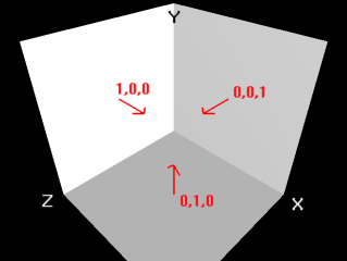
Now I have bad news for you. This is not all :). Although it seems we can do nothing more with the light, and it should all work OK now, it probably wouldn't. As the light is entity based on rays, we must say to TBGL the vector perpendicular to the surface of the polygon.
This vector is called "normal vector", and it's defined this way:
|
tbgl_Normal x, y, z |
It should be defined before every vertex of the poly. To explain this topic more, look at this image:
You are feeling better now ? I'm happy to hear that, but now I will scare you again :).
How the vector looks, if the polygon is not displayed in simple positions as on the image ?
You must calculate it !
Here I have 2 good news, so you can relax for ... few seconds.
The first good thing is, that you do not have to do this calculations for built-in primitives mentioned in the begining of this lesson.
The second one is, that in case of polys, where you have to define it, you don't have to manualy scale the vector to have unit lenght, that's done by TBGL automatically.
And now some simple math theory, which will help you with your normal vector task.
Let's presume we have triangle based polygon. To calculate the normal vector you just have to perform vector multiplication of vectors defining the plane.
Let's define vector u and v which will produce the normal vector n.

Then
|
n = ( (uy * vz - uz * vy), -(ux * vz - uz * vx), (ux * vy - uy * vx) ). |
For example, for control we will calculate normal vector for polygon in plane XZ:
|
u = ( 1, 0, 0 ) v = ( 0, 0, 1 ) n = ( (0*1 - 0*0), -(1*1 - 0*0), (1*0 - 0*0) ) = ( 0,-1, 0 ) |
Seems to be correct :). I strongly recommend to save the normal data in some array to not bother the CPU in every frame with this calculations.
So I have last information for you. Sometimes, especially in case of surfaces created by connected polygons it is wise to calculate the vector not just for each polygon individually, but it's good to build it according to the plane created by all neighbour vertexes.
Watch the difference on this image:
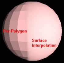
The first surface is designed using "traditional" way of computing normals, the second one uses smart technique to achieve better look.
Hope you have now clear idea how it works. The bundled source codes should put some light on this topic :)
To test it just download this source code: Lesson 6 source code
| Previous | Home | Next lesson |
© Petr Schreiber, 2006